British Pounds
How to Build A Peg Perego Polaris Ranger RZR Green Shadow 24V Kids Ride On - Along with a Full Parts List & Instructions

Assembly Guide of How to Build A Peg Perego RZR Polaris Ranger Green Shadow 24V Kids Ride On - Along with a Full Parts List & Instructions
If you've got a new PegPerego Polaris Ranger Green Shadow RZR24Vand you want some help building it, this blog post is the place to start!
As well as a full parts list for the Peg Perego RZR Polaris Ranger Green Shadow 24V at the bottom of this post along with images from the manual and photos of the key steps, we'll go into detail on every element of the assembly of your RZR. If you have a second hand RZR that you are restoring, then this page is also a great resource for you.
Use the parts list at the bottom of the post to identify any missing parts, then just click the links to order, or click here to get in touch with our friendly team of experts if you need more advice.
So, on with the main event - how exactly do you assemble a Peg Perego RZR Polaris Ranger Green Shadow 24V? All you'll need to start is around 20 minutes and a Phillips Screwdriver.
Assembling your Kids Ride on Peg Perego RZR Polaris Ranger Green Shadow 24V
Start by separating out the pieces and bags of smaller components, and make sure you have your manual handy. If you have mislaid your manual, click here to download a new copy. Put the sticker sheet to one side, as you won’t need this until the very end, and you don’t want to risk creasing it.
This guide follows the same steps as the manual, and we’ll include pictures from the manual along with explanations.
Tools required: spanner (included with RZR), Philips head screwdriver.
You need to charge your RZR battery for 12 hours before first use, so we recommend completing steps 1-4 as soon as you can, so that you can leave the battery charging. You can then continue the assembly from Step 5 once the battery has been fully charged.
Your RZR has been packed for shipping, and to protect it during transit some prts are fixed together and will need to be separated. As such, the first step in building your RZR is to remove the four fixing screws from the two seat base sections, as shown in the image below:

Now remove the seat base, working from the battery side, taking care to remove the connectors from the slots as indicated in Step 2 below. Once this is done, remove the other seat base as shown in Step 3.

With the seat bases removed, it's now time to take out the battery and the battery base as shown in Step 4. We recommend charging the battery for an uninterrupted 12 hours before the first drive, so put it on to charge now.

Next you will need to remove the fixing screws from the two rear base fixtures as shown in Step 5, which will allow you to remove the two rear base locks, as shown in Step 6.

Now take a moment to study the diagram below for Step 7, then as shown pull the base in the direction of the arrow to fully remove the motor unit. This is the last part you'll need to remove, and we can now get on with fully constructing the vehicle.

We'll start as shown in Step 8 below by repositioning and screwing on both rear base locks. You can now insert the trailer attachment to the rear. This can be tricky, but take a moment to look at Step 9 below, which shows how to align all four holes. Once aligned, tighten the two upper and two lower screws

Now, take the two shock absorbers and insert them into the holes in the bodywork as shown in Step 10, then attach the shock absorbers to the bodywork with the two pins, one on each side, as shown in Step 11. Your RZR is supplied with a pair of spare pins, so put these to one side, and keep them with the manual as they may come in handy if you ever crack a pin.

Now it's time to attach the exhaust pipe as shown in Step 12. Step 13 shows how to attach the screw to fix the exhaust pipe into position.


With the exhaust installed, you can now position the rear box as shown in Step 14. As Step 15 shows, you will need to insert the tabs on the front of the rear box into the bodywork. There are two tabs on each side, so ensure these all pass through cleanly. Next fully insert the two metal tubes as in Step 16, installing one on each side, then complete the rear box installation by fixing it into position with three screws as shown in Step 17.


This can be a little tricky so we recommend pressing the pin as shown below in Step 18 to help align the screw holes.

Now we are ready to begin installing the side supports. Start by studying Step 19 below to ensure that the side supports match the grilles:

Once you've confirmed the side supports are in the correct orientation, start the installation by hooking the lower ring of the support onto the grille, as shown in Step 20 below, then complete the attachment process by fitting the

upper ring, making sure the front part of the grille is inserted properly. in case you are finding this step tricky, image number 22 below shows both the incorrect and correct positions. Picture A shows the front part of the grille when it is not fitted correctly, and Picture B shows the grille fitted correctly.

The next parts we are installing are the side panels. These are temporarily screwed to the body for safety, but can now be removed. See Step 23 below and use it as a guide to remove the two upper screws, then take the side panels off the bodywork.

Now you're ready to insert the side guards as shown in Step 24, taking care to fit the parts with the grid extending towards the outside. Complete the attachment by pushing the side guards forward until they click into position, then replace the side panels onto the main body as shown in Step 25.


Our next part is the cargo box. This is very simple, and only requires four screws. First place the box in position and then follow Steps 26 and 27 to secure the box with screws, two on the upper profiles, two protruding through the cabin.

With the cabin in place, we can now fit the rear cover plate shown in Step 28. This can be a little tricky, so take your time to study Step 29 below. It shows four lettered points which all have to line up. These are:
A - Housing for attachment to bodywork.
B - Housing for the insertion of metal tubes.
C - Housing for the insertion of the exhaust pipe.
D - Tabs for fixture to bodywork.

Ensure all four are correctly aligned, then lift the upper part of the rear cover plate so that the tabs can properly fit into the slots as shown in Step 30.

Now that the rear cover plate is in the correct position, secure it with two screws as shown in Step 31, and a final screw under the exhaust pipe as in Step 32:

With the rear cover fully installed, we no move onto the roll bars. Start by fitting one of the vertical pieces. Note that the two verticals are mirrored, so make sure you fit the right way round, as shown in Step 33. Note that Step 33 shows the left side of the vehicle. Once the vertical is in place, rotate it until it is at the right angle to accept the side bars, as is Step 34, then screw the verticals into position as in Step 35.


With the vertical bars in place, it's time for the side bars. Look at Step 36 below, and once the side bars are in position, fix them in position with a screw.

Now we'll fit the rear tubes. Note that the two rear tubes are mirrored, so make sure you have them the right way round. When they are in place, as in Step 37, secure them with screws at the top as shown in Step 38, and the bottom, as shown in Step 39.

The next part of the rollcage is the horizontal bar that links the rear tubes. Start by placing the clamps on each of the rear tubes as shown in Step 40, making sure they are properly aligned, as shown in Step 41. Fit the central bar into each of the clamps as shown in Step 42, then insert a screw and a nut in each hole as in Step 43, then tighten as in Step 44.


Next it's time for the top of the rollbar. This needs to be the right way round, as shown in Step 45 below. Make sure to check the image and identify the A and B sides using the detailed view. A should face forward, while B should face the rear of the vehicle. With the rollbar top in place, you can fix it into position by installing the tops of the seatbelt harnesses as shown in Step 46. The screw should pass through both the seatbelt mounting and the top bar, securing both and adding strength to the system.


Now attach the three included plastic light mounting rings to the rollbar as shown in Step 47, ensuring that the rings are level and facing the direction shown in the image. Now use the rings to mount the three fog lights on the roof bars and attach them with the screws provided, as in Step 48. This completes the assembly of the roll bar.

Next we'll fit the cargo net. Start by using three screws to fit the bottom of the harness to the base of the brush guard, as shown in Step 49, then secure the harness to the upper part of the roll cage, securing it by looping the long ends over the roll bar, then using the fasteners as shown in Step 50.

With the cargo netting installed, it's now time to move on to the front cover plate. There are five key points that need to line up with the corresponding parts on the bodywork. The five key points are:
A - Tabs for fixing to the bodywork.
B - Housing for engagement with the bodywork.
C - Housing for attachment to the base
D - Tab for engagement to the hood.
E - Hole for inserting the front bumper.
These are marked A, B, C, D, and E in Step 51 below. Position the front cover plate by inserting the points indicated with the letters A and B into the bodywork. Put a hand inside the bodywork at point B and squeeze the body and plate together to click them into place (this is shown in detail in Step 52 below, in the zoomed circle).


With A and B clicked into position, press on the middle of the front cover plate so that tab D click into position, as in Step 53, then press the lower part of the cover so that the two tabs at C also click securely into position as in Step 54.


Now that the cover is properly in position, it's time to install the front bumper. Slide it onto the two mounting pins as shown in Step 55 below. The next step can be tricky, but the image in Step 56 shows clearly what is needed. There is a protruding tab at the bottom of the bumper, which must pass cleanly into the slot marked E. Once it's slotted into place, secure with a screw as in Step 57, then complete the front bumper installation by securing it with two screws as shown in Step 58.


Your RZR will look like it's taking shape - we're nearly there, and now is a good time to make a cup of tea or take a quick break, especially if you have not yet charged your battery for the recommended 12 hours. Once you're ready to continue, and have a fully charged battery ready to go, it's time to assemble the steering wheel. Do this by taking the front and back parts of the wheel and pressing them carefully together as in Step 59, ensuring that the catches are properly aligned. Once these two parts are securely clicked together, insert the central cap into the recess on the front of the wheel as in Step 60.

Now it's time to install the steering wheel. First remove the plastic protectors from the steering shaft as shown in Step 61, then slide on the steering wheel, aligning the holes in the steering shaft and the steering wheel collar as shown in Step 62. The steering wheel is secured with a threaded pin and a bolt as shown in Step 63. Make sure you insert the bolt through the hexagonal hole, and the threaded pin into the circular hole, holding the bolt to keep it in place.

Next, install the passenger safety handle onto the dashboard as in Step 64, and attach with screws as shown in Step 65.

The next part to fit is the petrol cap, which simply snaps into position as shown in Step 66.

Now take the seat bases you removed earlier. Start by re-inserting the driver's side seat base as shown in Step 67, then, once it's in position, insert the charged battery into the compartment under the passenger seat as in Step 68. Once this is done, thread the battery cable and the matching cable in the vehicle through the holes in the passenger seat base as shown in Step 69 and slide the passenger seat base into position as in Step 70. You can now connect the battery and system cables together as shown in Step 71.


With both seat bases in position, secure them with two screws each as shown in Step 72.

Next we'll install the short safety belt receiver sections, inserting the tabs as shown in Step 73. Make sure the safety belt buckle buttons are facing the gear lever, as shown in the image.

With the seat bases secured and the safety belt receivers in place, it's time to fit the seats. Start by removing the knobs on the seat bases as shown in Step 74. Now turn to your seats and pull the seat covers over them as shown in Step 75. Next, position the seat, then lift the front of the seat and line up the holes with the bolts you removed the knobs from in Step 74, noting that there are two different positions as shown in Image 76. For most young riders, position 1 is ideal, while for taller or older children, position 2 will provide more leg room.


With the seat in position, screw the knobs back into the seat bases as shoiwn in Step 77, locking the seat into place, then lower the seat front as shown in Step 78. Finally, tighten the safety screw on each seat as shown in Step 79.


The next part to fit is the windscreen. Start by fitting the two parts of the windscreen together as shown in Step 80, then screw together as shown in Step 81.

With the windscreen assembled, you now need to place it onto the hood of the vehicle, ensurig you properly align the three central tabs as shown in Step 82. Once it's properly aligned, use the supplied screws to secure the windscreen in place as shown in Step 83.

Now that the windscreen is in place, it's time for the final push - all that's left is to fit the vehicle's wheels, then you'll be ready to drive. Start by removing the protectors from the rear axle as shown in Step 84, then insert the axle into the vehicle as shown in Step 85.


With the axle in place, it's time to prepare the rear drive wheels. These are prepared by fitting one of the drive hubs to the inner hub of the rear wheel, as shown in Step 86. Please note that the two larger wheels are the rear wheels, and the two smaller wheels are the front wheels. Once you have the drive hubs installed, slide the first rear wheel onto the axle with the driver hub facing inwards, as shown in Step 87.

With one wheel on the axle, slide a washer on as shown in Step 88, then fasten the wheel with a nut, using the included spanner. With one wheel secured, repeat the process on the other side, sliding the wheel and drive hub onto the axle, then a washer, then finally tightening with a nut.

Now it's time for the front wheels. Start by removing the protectors from the front axle as shown in Step 90. Now slide a washer onto the axle, as shown in Step 91, then slide on a wheel, as in Step 92, then another washer, as in Step 93. Finally, fit a nut to the end of the axle, and use the included spanner to tighten it as in Step 94. Once one front wheel is fitted, repeat the process on the other side.


The final step of construction is to add the four hubcaps to the wheels. These simply snap into place, as shown in Step 95.

Once this is completed, it’s time to place the stickers on the body. If you tear any of your stickers, or would like some extra ones, we sell full RZR sticker sheets at this link.
This completes the construction of your Kids Ride on RZR, and now all you need to do is charge your battery and connect it to the vehicle. The first battery charge is a very important step, as it conditions the battery cell, ensuring you get maximum battery life and drivetime. We recommend a 12 hour initial charge with no interruption. Once this is done, simplt slide the battery into the battery bay in the front of the vehicle, and connect the cable to the matching connector inside the battery compartment. Finally, close the compartment and screw it shut.
The RZR comes complete with a simple parental speed limiter system which allows you to lock off the top gear. To allow use of the top gear, simply undo the screw in the gear selector and move it into one of the two positions, as below:
The position shown in step 46 allows only first gear and reverse, while the position in 47 allows reverse, low and high gears to be used.
If you need any further help with assembling your RZR, don’t hesitate to get in touch with our friendly team, who will be happy to help. If your RZR is a second hand item, we are happy to help, both with guidance and in supplying any missing or worn parts. We stock all parts for the Peg Perego RZR 24V, and you can click here to see them all. If you can't find the part on our site, just click here to get in touch and we'll be happy to assist.
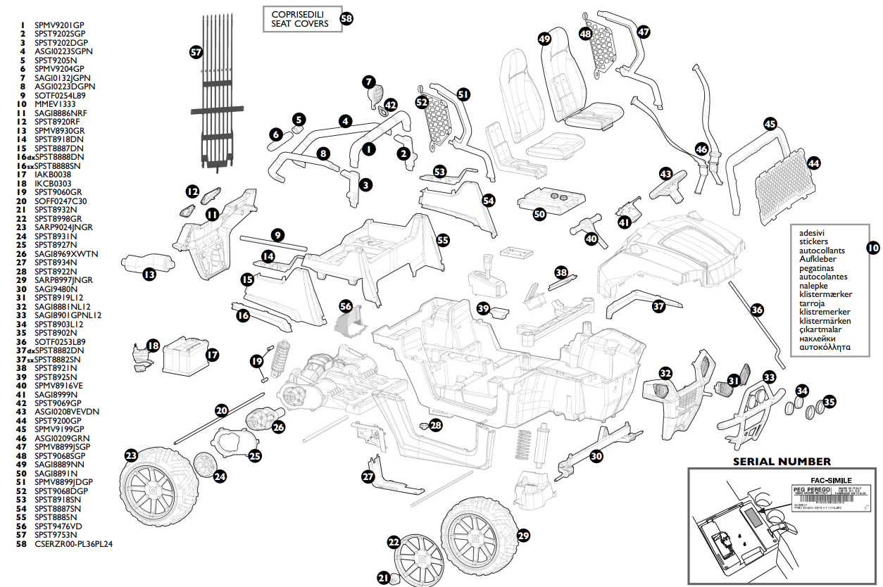
24V Ride on RZR Complete Parts List:
The diagram below shows all the 24V RZR parts - to find the part ID, just use the table below the diagram.